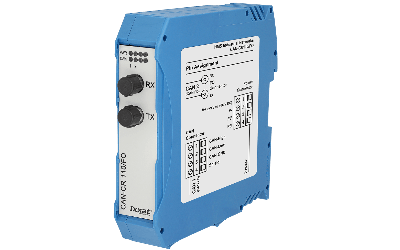
CAN / CAN FD repeater with screw terminals and fiber optic connector
Ixxat repeaters are used to establish a physical coupling of two or more segments of a CAN or CAN FD bus system. They can be used to implement tree or star topologies as well as for long drop lines. In addition, network segments can be electrically decoupled using a galvanically isolated repeater.
The CAN-CR110/FO is used for galvanic isolation of two segments of a CAN / CAN FD network. As a special feature, the repeater separates a defective segment from the rest of the network, allowing the remaining network to continue working. After the fault has been eliminated, the segment is automatically switched back to the network. The galvanic isolation is provided for the CAN / CAN FD segments as well as for the power supply.
Increase reliability
CAN and CAN FD repeaters increase your system reliability with almost no influence on real-time behavior.
For harsh environments
Ixxat repeaters decouple CAN or CAN FD segments galvanically up to 4 kV and are also available as variants with fiber optics.
Save costs
Easier wiring and reduction of cables reduces the cost of your system.
Product Information
- Fiber optic enables transmission in areas with high electromagnetic disturbances
- CAN and CAN FD interfaces in one device
- Cost savings due to simple wiring
- Increased system reliability
- Almost no influence on real-time behavior
- CAN-CR110/FO
- User manual
| Display | Transmit and defective segment (two duo LEDs, one for each segment), Power (one LED) |
| CAN bus interface | ISO 11898-2 with CAN choke. Two screw terminals. CAN variant available with and without integrated CAN termination. |
| CAN bitrates | Up to 1 Mbit/s |
| CAN FD bus interface | ISO CAN FD and nonISO CAN FD |
| CAN FD bitrates | Arbitration rate up to 1000 kBit/s, data rate up to 8000 kbit/s. The data rates are verified by tests. User-defined bit rates are possible. Attention: The maximum data rate can be exceeded depending on the concrete operating conditions (cable length, settings made, remote stations,…), but it can also not be reached. |
| Delay | typ. 300 ns (corresponds to ~60 m bus length) between the wire connection of a FO Repeater through the fiber optic cable to the wire connection of a second FO Repeater (not including the signal delay time of the fiber optics, which is ~5 ns/m) |
| FO transmitter | Broadcom HFBR 1404Z, 820 nm |
| FO receiver | Broadcom HFBR 2402Z, 820 nm |
| FO line | F-SMA connector; Multi-mode fiber optic line (only glass); recommended: 50/125 µm, 62,5/125 µm, also compatible with: 100/140 µm, 200 µm (pay attention to max. line length) |
| Max. line length between two FO repeaters |
50/125 µm: 1500 m, 62,5/125 µm: 2000 m |
| Power supply | 9-36 V DC, typ. 70 mA, max. 100 mA, through terminals |
| Galvanic isolation | 1 kV DC / 1 sec, 500 V AC / 1 min; CAN 1, CAN 2 and the power supply is galvanically isolated from each other. |
| Certification | CE, FCC |
| Temperature range | -20 ºC … +70 ºC |
| Housing, size | Plastic enclosure, 22.5 x 105 x 120 mm |
| 1.01.0210.11020 | CAN-CR110/FO, with the bus termination resistor |
| 1.01.0210.11220 | CAN-CR110/FO, without bus termination resistor |
Book your product
We are fully committed to providing our customers with the very best products and customer service. We believe in going the extra mile to ensure that each customer is satisfied with our products and solutions. We have the experience and the reputation in the field to deliver the products customers need to expedite their projects and assure quality every step of the way.

Our expertise lies in establishing, maintaining, and leveraging plant data for business benefit. Through our innovative solutions, we work alongside you to streamline processes, enhance efficiency, and reduce costly downtime.
CONTACT US
Main: +27 (11) 548 9960
Sales: +27 (11) 548 9970
SOCIAL MEDIA
