
Reliable optical data transmission in PROFIBUS networks
The Anybus ComBricks is the first PROFIBUS-based automation system that unites repeaters and permanent monitoring in a web browser. With an evolving industry using more mixed architecture networks, users are able to integrate ComBricks into their PROFINET network via Osiris, allowing them to monitor everything from one single cross-platform.
The ComBricks Fibre Optic Ring module for multi-mode technology (ComBricks FO Ring MM) ensures reliable optical data transmission in PROFIBUS networks. This multifunctional module is specifically designed to create optical redundant ring topologies with multimode fibre optics. It allows long cable distances of up to 5 km and galvanic isolation between devices and segments. The ComBricks FO Ring MM module is especially suitable for applications in heavy EMC environments such as oil & gas, waste treatment and cranes.
The ComBricks FO Ring MM module contains diagnostic LEDs which indicates the detection of a low level on the optics. Just like any other communication module, the channels are connected directly to the ProfiTrace OE core in the Head Station. An advanced email functionality will alert you when faults like low-level or broken rings arise. Because busmonitor data is directly available in the web server, it allows technicians to optimally maintain a PROFIBUS installation.
ComBricks FO Ring MM can be placed side by side with repeater modules allowing spur line diagnostics. It can also easily be used as a fully dedicated fibre optic module mixed with copper segments. The advanced 12 Mbps core of the fibre optic module can be cascaded unlimitedly with other fibre modules.
Product Information
Distinctive features
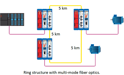
Figure 1 – Ring structure with multi-mode fibre optics
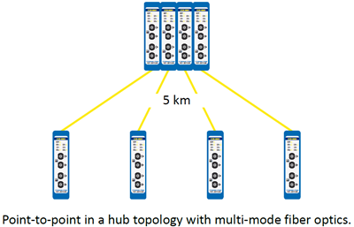
Figure 2 – Point-to-point in a hub topology with multi-mode fibre optics
Dimensions
| L x W x H: | 146 x 25 x 101 mm (including backplane) |
| Weight: | 121 g (excluding plug-able fibre optic connector and packing material) |
| Mounting DIN-rail type | 35mm × 7,5mm (EN 50022, BS 5584, DIN 46277-3) |
Ambient conditions
| Operating temperature range |
0° to +60° Celsius (for mounting position see manual) 32° to +140° Fahrenheit |
| Isolation class | IP 20 (IEC/EN 60529, DIN 40050) |
Backplane
| PROFIBUS networks | 4 (set by dipswitches or web server) |
| Modules | Max. 10 (positioned in the first 10 slots) |
| Power supply | Provided through the backplane |
| Typical backplane current at 5.75 VDC | 400 mA (at 5.72 VDC) |
| Max. backplane current at 5.75 VDC | 600 mA (at 5.72 VDC) At this current consumption the module is switched OFF from backplane. Occurs when module is faulty, e.g. internal short circuit. |
| Compatible backplane units |
101-200011, 101-200022, 101-200023, 101-200024, 101-200027 |
| Head Station firmware | 1.288 and higher |
Protocol specifications
| Supported Protocols | DP-V0, DP- V1, DP-V2, FDL, MPI, FMS, PROFIsafe, PROFIdrive and any other FDL-based protocol | ||||||||||||||||||||||||||||||||||||||||||||
| Address | No bus address required | ||||||||||||||||||||||||||||||||||||||||||||
| Transmission speed | 9.6 kbps … 12 Mbps (including 45.45 kbps) | ||||||||||||||||||||||||||||||||||||||||||||
| Transmission speed detection time | Auto detect (< 10 s detection and 50 s baudrate switchover time) | ||||||||||||||||||||||||||||||||||||||||||||
| Total delay ring structure |
TSLOT ≥ MaxTSDR + ((FOlength FOlength = Total length of fibre optic cable in the ring in km FOdelay = Delay of fibre optic cable per km in bit times (see table) NFO-modules = Number of fibre optic modules in the ring Ndelay = Delay of one fibre optic module (see table) The delay time is multiplied by 2 for a request and response message.
Note FOdelay = (FOcable_length / FOcable latency ) / Bittime example FOdelay, 1km, 1.5Mbps: (1000 m / 200 µsec/m) / 0.666 µsec = 7.5 Tbit/km Example 1: 1.5 Mbps, 5 km FO cable (total ring length), 6 FO ring modules TSLOT ≥ MaxTSDR + ((FOlength x FOdelay) + (NFO-modules x Ndelay)) x 2 TSLOT ≥ 150 + ((5 x 7.5) + (6 x 9)) x 2 ≥ 333 bit times Example 2: 6 Mbps, 25 km FO cable (total ring length), 10 FO ring modules TSLOT ≥ MaxTSDR + ((FOlength x FOdelay) + (NFO-modules x Ndelay)) x 2 TSLOT ≥ 450 + ((25 x 30) + (10 x 25)) x 2 ≥ 2450 bit times |
||||||||||||||||||||||||||||||||||||||||||||
| Jitter per message frame |
0.0625 Tbit at 9.6 Kbps – 3 Mbps 0.125 Tbit at 6 Mbps 0.25 Tbit at 12 Mbps |
||||||||||||||||||||||||||||||||||||||||||||
| Deviation | 2 Tbit times for received messages is allowed and is corrected to nominal speed when transmitted (over the complete message) |
Fibre optic specifications
| Fiber Optic wavelength | Multimode 1310 nm |
| Cable type |
Multimode Fiber G62.5 / 125 µm (OM1 compatible) Multimode Fiber G50 / 125 µm (OM2, OM3, OM4, OM5 compatible) |
| Cable length | Max. 5 km (baudrate independent) |
| Optical budget | 13dB |
| Optical Loss | 2dB per km |
| Connectors | 4 x ST/BFOC (2 channels) |
| Topologies | Ring, point-to-point (direct, hub, split, star) |
| Cascading depth |
No limit, only bus parameter limitation of the master
|
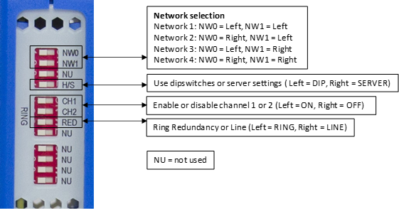
Dipswitches
LEDs
| OFF | Blinking | ON | |
| RDY | The module has NOT been powered/initialised yet. | Head Station is initialising or updating the module. | The module has been initialised and is operational |
| RX1 / RX2 | NO signal or NO valid telegrams detected on this channel, or the channel is off. | 1 or more devices are communicating on this channel. | A fibre optic cable is connected and the link is established correctly |
| LV1 / LV2 | The signal quality is good, or the channel is off. | Not possible | Low signal, received messages can still be decoded |
| ER1 / ER2 | No errors or the channel is off. | Not possible | No baudrate detected or no connection/signal |
Standard and approvals
| CE |
EMC Directive 2014/30/EU, class B Digital Device RoHS Directive 2011/65/EU |
| FCC | 47 CFR 15, Unintentional Radiator, class B Digital Device. |
| UL |
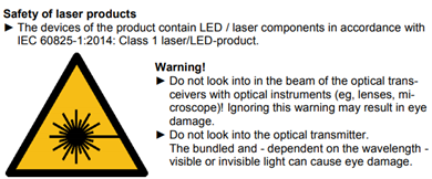
Report reference: E468970 Standards for safety: UL 508 – Industrial Control Equipment CSA C22.2 No. 142-M1987 – Industrial Control Equipment Complies with 21 CFR 1040.10 and 1040.11, Class 1 (I) except for deviations pursuant to Laser Notice No. 50, dated June 24, 2007 |
| Order Codes | 101-201530 |
| Included Components | Anybus ComBricks, backplane socket |
| Warranty | 1 year |
Book your product
We are fully committed to providing our customers with the very best products and customer service. We believe in going the extra mile to ensure that each customer is satisfied with our products and solutions. We have the experience and the reputation in the field to deliver the products customers need to expedite their projects and assure quality every step of the way.
Our expertise lies in establishing, maintaining, and leveraging plant data for business benefit. Through our innovative solutions, we work alongside you to streamline processes, enhance efficiency, and reduce costly downtime.
CONTACT US
Main: +27 (11) 548 9960
Sales: +27 (11) 548 9970
SOCIAL MEDIA