
An RS 485 PROFIBUS repeater module with an integrated quality oscilloscope for 12 Mbps with diagnostic LEDs and a redundancy feature
The Anybus ComBricks is the first PROFIBUS-based automation system that unites repeaters and permanent monitoring in a web browser. With an evolving industry using more mixed architecture networks, users are able to integrate ComBricks into their PROFINET network via Osiris, allowing them to monitor everything from one single cross-platform.
The Anybus SCOPE Repeater is a 1 Channel RS 485 PROFIBUS diagnostic repeater module with an integrated quality oscilloscope for 12 Mbps with diagnostic LEDs and redundancy feature. Bus connection is utilised by screw terminals and additional DB9 connectors.
The repeater channel and the integrated oscilloscope are directly connected with the ProfiTrace OE core in the 1B/1C Head Station. Scope images and bus monitor data are directly available on the web server.
The advanced 12 Mbps core of the repeater module can be cascaded unlimitedly and has increased RS 485 strength. The data traffic is constantly monitored for glitches which are digitally filtered out. It has on-board switchable termination and is able to drive 31 devices.
Product Information
Distinctive features
Your benefits
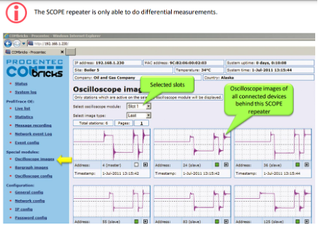
Figure 1 – Oscilloscope images from all devices
Dimensions and weight
| L x W x H: | 137 x 25 x 103 mm (including backplane, per module) |
| Weight: |
120 g (excluding plug-able connectors, backplane and packing material) |
| Mounting DIN-rail type | 35mm × 7.5mm (EN 50022, BS 5584, DIN 46277-3) |
Ambient conditions
| Operating temperature range |
-20o … +60o Celsius (for mounting position see manual) -4o … 158o Fahrenheit |
| Isolation class | IP 20 (IEC/EN 60529, DIN 40050) |
Backplane
| PROFIBUS networks | 4 (set by dipswitches or web server) |
| Modules | 10 (positioned in the first 10 slots) |
| Power supply | Provided through the backplane |
| Typical backplane current consumption | 400 mA (at 5.72 VDC) |
| Max. backplane current consumption | 600 mA (at 5.72 VDC) At this current consumption the module is switched OFF from backplane. Occurs when module is faulty, e.g. internal short circuit. |
| Compatible backplane units |
101-200011, 101-200022, 101-200023, 101-200024, 101-200027 |
Protocol specifications
| Supported Protocols |
DP-V0, DP- V1, DP-V2, FDL, MPI, FMS, PROFIsafe, PROFIdrive and any other FDL-based protocol |
| Address | NO bus address required |
| Transmission speed | 9.6 kbps .. 12 Mbps (including 45.45 kbps) |
| Transmission speed detection | Auto detect (< 10 s detection and 50 s baudrate switchover time) |
| Data delay time |
At baudrate Normal mode Redundunt mode 9.6 – 500 kbps 2.8 Tbit 13.8 Tbit 1.5 Mbps 3.2 Tbit 14.2 Tbit 3 Mbps 3.9 Tbit 14.5 Tbit 6 Mbps 4.6 Tbit 15.6 Tbit 12 Mbps 6.4 Tbit 17.4 Tbit |
| Deviation | 2-bit times (over the complete message) for received messages is allowed and is corrected to nominal speed when transmitted. |
Oscilloscope specifications
| Frequency | 192 MS/s |
| Resolution | 50 mV |
| Differential range | -6.436 .. 6.436 V |
PROFIBUS cable specifications
|
Cable lengths
|
1200 m at 9.6 kbps to 93.75 kbps 1000 m at 187.5 kbps 400 m at 500 kbps 200 m at 1.5 Mbps 100 m at 3 Mbps to 12 Mbps |
| Wire diameter (for the screw terminals) | < 2.5 mm2 |
| Wire type | Stranded or solid core |
| Number of devices | Maximum 31 devices per channel (busload) |
| Termination |
Integrated and switchable Powered according to PB RS 485 (390/220/390 Ohms) |
| Redundancy | Yes, maximum 10 cables activated by switch |
| Cascading depth | No limit (only limited by busparameter of the master) |
| Cascading units |
With standard busparameters: At baudrate Normal mode[units] 9.6 kbps 7 19.2 kbps 7 45.45 kbps 42 93.75 kbps 7 187.5 kbps 7 500 kbps 17 1.5 Mbps 23 3 Mbps 19 6 Mbps 16 12 Mbps 15
Formula to calculate number of cascading units with adjusted Tslot : Cascading units = (Tslot – maxTsdr) / (2 × Tdata_delay_time) Tdata_delay_time is described in protocol specifications on previous page. Example 1.5 Mbps, normal mode: Cascading units = (300-150) / (2×3.2) = 23 |
Connector Lay-out
| PROFIBUS DB9 CH1 |
D Sub connector, 9 contacts (PROFIBUS specification) Pin 1: N.C. Pin 5: GND Pin SH is connected internally to the DIN rail with spring-loaded contact. The pin I is connected internally with 10nF/1MOhm to shield. |
LEDs
| RDY: Ready | The module is ready for operation (ON) |
| RX: Receiving | Receiving telegrams (blinking) |
| SW: Switch Network Termination | Network Termination active (ON) |
| HWE: Hardware Error | Internal repeater error (ON contact HMS Technical Support) |
| ER: Error Receiving | No, or bad receiving telegrams detected (ON or blinking) |
| MIN: Minus | No, or bad receiving telegrams detected (ON or blinking) |
| TERM: Termination Voltage |
Signal amplitude of the telegrams is too low < 2.5 V (ON) Idle voltage too low <0.95 V or >1.26 V (ON) Alarm values can be changed through the web server. |
Dipswitches
|
NW0 NW1 LEFT LEFT RIGHT LEFT LEFT RIGHT RIGHT RIGHT
RED LEFT RIGHT
H/S LEFT RIGHT |
PROFIBUS Network 1 2 3 4
Redundancy OFF ON
Settings Hardware Software |
Standard and approvals
| CE |
EMC Directive 2014/30/EU, class A Digital Device RoHS Directive 2011/65/EU |
| FCC | 47 CFR 15, Unintentional Radiator, class A Digital Device. |
| UL |
Report reference: E468970 Standards for safety: UL 508 – Industrial Control Equipment. CSA C22.2 No. 142-M1987 – Industrial Control Equipment |
Others
| Head Station firmware | At least version 1.260 |
| MTBF | 1123748 hours, at 30o Celsius, IEC TR 62380 |
| Order Codes | 101-201210 |
| Included Components | Anybus Combricks, backplane socket |
| Warranty | 1 year |
Book your product
We are fully committed to providing our customers with the very best products and customer service. We believe in going the extra mile to ensure that each customer is satisfied with our products and solutions. We have the experience and the reputation in the field to deliver the products customers need to expedite their projects and assure quality every step of the way.
Our expertise lies in establishing, maintaining, and leveraging plant data for business benefit. Through our innovative solutions, we work alongside you to streamline processes, enhance efficiency, and reduce costly downtime.
CONTACT US
Main: +27 (11) 548 9960
Sales: +27 (11) 548 9970
SOCIAL MEDIA